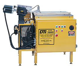
Pocket
Cutter/Screw Insertion Machine DTI 2000
The machine is designed to automatically route a pocket, drill a pilot hole and insert a screw into face frame rails of any width or length. Cycle time for all three operations will be 4 seconds or less.
Features
- Working surface is approximately 2 ft. X 3 ft.
- Pocket is routed at 15 degree
- Pocket width is 7/16 inches
- Pilot hole for screw is under sized (#29 0.136) so the screw
doesn't fall out during transporting of Complete parts.
- The screw is inserted to a depth so the screw point is to
the outer edge but not protruding
- A back fence will square the rail
- Adjustable end stops will position the rail for the pocket
location NOTE: The end stop and back fence have sensors, which
have to be made for the machine to cycle. This insures that
the rail is in place before the machine is cycled
- Hold down clamps will secure the rail while the process is
being done
- Opti-touch buttons will be used for operator safety
(optional foot switch or single palm button)
- Dust collection hook-up system
|
|
Sequence of operation
- Operator sets the end stops to the proper positioning
- Operator places the rail up against the back fence and end stop
- Operator activates the opti-touch buttons (optional foot switch or palm button)
- The rail is clamped
- The router cuts the pocket
- The pilot hole is drilled
- The router assembly shifts bringing the screw inserter into position
- The screw inserter moves up putting the inserter guide into the pocket
- The screw is inserted to a pre-set depth
- The screw inserter moves down at the same time the clamp is released
- Operator moves the rail to the next position if additional pockets are needed, at the same time the screw and router assemblies shift back to the home position. NOTE: With the proper set-up two rails could be handled at a one time, applying one screw to each rail and rotating both parts 180 degrees. This eliminates some handling.
- Operator repeats the process
Components
- 1-PLC electrical controls
- 1-12" cast aluminum feeder bowl
- 1-Feed mechanism for 1 ¼혻 or 1 ½ screw
- 1-Welded tubular steel table
- 1-Z axis thruster assembly to raise and lower screw inserter
- 1-X axis thruster assembly for moving the screw inserter and router left to right
- 1-Thruster assembly to move router on 15 degree angle
- 1-Back fence
- 2-Adjustable end stops
- 1-Hold down clamps
- 1-Lot of pneumatic hardware, valves, tubing, etc.
- 1-Screwdriver platen assembly with the following
- ARO 1900-RPM air motor
- Tool holder
- IKO linear bearing and rail assembly
- Screwdriver bit and extension
- Air cylinder with flow controls
- Barrel and screw collet assembly
- Barrel holder
- Steel platen for mounting the above
- Screw carrying tube
- 1-3/4 HP, 3,600-RPM heavy duty drill motor for pilot table
- 1-2 HP, 18,000-RPM Purske motor with a heavy duty router spindle, ½ collet for a 7/16 router bit
- 1-Dust collection hook up
- 1-Manual with wiring diagram, assembly drawings and parts list
- 1-Day installation and training
Electrical Requirements: 440 volts three phase
Air Requirements: 90 PSI
|